Chapterبەش 4 · Lectureوانە 4.1
Lab: Blink an LED and Build a Traffic Lightتاقیگە: LEDـێک بترووکێنە و گڵۆپێکی هاتوچۆ دروست بکە
Your first hands-on Arduino lab. Learn why every circuit needs a way back to GND, which leg of an LED is which, how to choose its resistor with Ohm's law for the UNO R3, UNO R4 and MKR WAN 1310, and what pinMode() and digitalWrite() do. Then blink an LED, see why delay() blocks, and build a traffic light — after spotting what is wrong with its first version.
یەکەم تاقیگەی دەستیی . فێر ببە بۆچی هەموو ڕێگایەکی گەڕانەوەی بۆ GND پێویستە، کام قاچی چییە، چۆن بە بۆ UNO R3، UNO R4 و MKR WAN 1310 هەڵدەبژێریت و pinMode() و digitalWrite() چی دەکەن. پاشان بترووکێنە، بزانە بۆچی delay() ڕێگرە و گڵۆپێکی هاتوچۆ دروست بکە — دوای دۆزینەوەی هەڵەی یەکەم وەشانەکەی.
What you will learnچی فێر دەبیت
- Explain GND and the complete circuit, and wire an LED with its resistor on a breadboard.
- Tell the anode from the cathode and choose an LED's resistor with Ohm's law for 5 V and 3.3 V boards.
- Use pinMode() and digitalWrite() with named pin constants.
- Blink an LED, read a timing diagram and explain why delay() blocks.
- Build a traffic light in the correct green → yellow → red order.
- GND و تەواو ڕوون بکەرەوە و لەگەڵ لەسەر ببەستە.
- لە جیا بکەرەوە و بە بۆ بۆردەکانی 5 V و 3.3 V هەڵبژێرە.
- pinMode() و digitalWrite() لەگەڵ پینی ناودار بە بەکار بهێنە.
- بترووکێنە، بخوێنەرەوە و ڕوون بکەرەوە بۆچی delay() ڕێگرە.
- گڵۆپێکی هاتوچۆ بە ڕیزبەندیی دروستی سەوز ← زەرد ← سوور دروست بکە.
What you will buildچی دروست دەکەیت
In this lab you make an LED blink, then build a traffic light from three LEDs. On the way you meet what every output circuit needs: a complete path back to GND, a resistor to protect the LED, and two Arduino functions, pinMode() and digitalWrite(). All circuits here are low voltage: the board takes 5 V from the USB cable.
لەم تاقیگەیەدا دەترووکێنیت، پاشان لە سێ گڵۆپێکی هاتوچۆ دروست دەکەیت. لە ڕێگادا ئەوە دەناسیت کە هەموو پێویستی پێیەتی: ڕێگایەکی تەواو بۆ گەڕانەوە بۆ GND، بۆ پاراستنی و دوو : pinMode() و digitalWrite(). هەموو لێرەدا نزمە: بۆردەکە 5 V لە کێبڵی وەردەگرێت.
What you needچیت پێویستە
- an Arduino UNO R3 or UNO R4 and a USB cable that carries data (an MKR WAN 1310 also works: see the resistor screen);
- a half-size breadboard and five or six jumper wires;
- three 5 mm LEDs: red, yellow and green;
- three resistors: 330 Ω for an UNO R3, 470 Ω for an UNO R4, 220 Ω for an MKR WAN 1310.
- Arduino UNO R3 یان UNO R4 و کێبڵێکی کە دەگوازێتەوە (MKR WAN 1310ـیش کار دەکات: سەیری پەڕەی بکە)؛
- نیو قەبارە و پێنج یان شەش وایەری پەڕینەوە؛
- سێ 5 ملم: سوور، زەرد و سەوز؛
- سێ : 330 Ω بۆ UNO R3، 470 Ω بۆ UNO R4، 220 Ω بۆ MKR WAN 1310.
No board yet? Build the same circuit in Wokwi or Tinkercad Circuits (No board? Simulate it). How the holes of a breadboard are connected is explained in The breadboard.
هێشتا بۆردت نییە؟ هەمان لە Wokwi یان Tinkercad Circuits دروست بکە (بۆردت نییە؟ هاوشێوەی بکە). ئەوەی کونەکانی چۆن بەیەکەوە بەستراون لە بریدبۆرد ڕوون کراوەتەوە.
GND and the complete circuitGND و سووڕی کارەبایی تەواو
Current flows only around a complete loop (A complete circuit). For an LED on an Arduino the loop is: output pin → resistor → LED → GND → back into the board. GND (ground) is the 0 V point of the circuit: every voltage is measured from it, and it is the road the current takes back. So every part — LED, sensor or module — needs at least two wires: one to a supply or a pin, one to GND. Without GND no current flows, and the part does nothing.
تەنیا بە دەوری سووڕێکی تەواودا دەڕوات (سووڕی کارەبایی تەواو). بۆ لەسەر سووڕەکە ئەمەیە: پینی ← ← ← پینی GND ← گەڕانەوە بۆ ناو بۆردەکە. GND () خاڵی 0 Vـی : هەموو لێیەوە دەپێورێت و ئەو ڕێگایەیە کە پێیدا دەگەڕێتەوە. بۆیە هەموو پارچەیەک — ، یان مۆدیول — لانیکەم دوو وایەری پێویستە: یەکێک بۆ سەرچاوەیەک یان پینێک، یەکێک بۆ GND. بێ GND هیچ ناڕوات و پارچەکە هیچ ناکات.
The pin at HIGH is a tank high up; GND is a tank on the floor. Water runs down the pipe and turns a small wheel (the LED); a narrow part of the pipe (the resistor) keeps the flow small. Take away the lower tank and the water has nowhere to go: nothing moves. Voltage is like the pressure that pushes; current is the flow.
پینی HIGH تانکییەکە لە بەرزی؛ GND تانکییەکە لەسەر زەوی. ئاو بە بۆرییەکەدا دێتە خوارەوە و چەرخێکی بچووک () دەسووڕێنێت؛ بەشێکی تەسکی بۆرییەکە () ڕۆیشتنەکە کەم دەکاتەوە. تانکییە نزمەکە لاببە و ئاوەکە شوێنی ڕۆیشتنی نامێنێت: هیچ ناجووڵێت. وەک ئەو پەستانەیە کە پاڵ دەنێت؛ ڕۆیشتنەکەیە.
Where the analogy stops workingسنووری ئەم نموونەیە
Water falls because of gravity; electric charge is pushed by voltage. The picture only shows why the path must be closed (Electricity as water in pipes).
ئاو بەهۆی کێشکردنی زەوییەوە دەکەوێتە خوارەوە؛ بە پاڵ دەنرێت. وێنەکە تەنیا پیشان دەدات بۆچی دەبێت ڕێگاکە داخراو بێت (کارەبا وەک ئاو لە بۆریدا).
The LED: a light that works one wayLED: ڕووناکییەک کە بە یەک ئاراستە کار دەکات
An LED (light-emitting diode) gives off light when current flows through it. Like every diode it lets current through in one direction only, from the anode (+) to the cathode (−) (Diodes and LEDs). On a new LED the anode is the longer leg; the cathode is the shorter leg, next to a flat edge on the rim. Put in the wrong way round, it simply stays dark: turn it round.
(دایۆدی ڕووناکیدەر) کاتێک پێیدا دەڕوات ڕووناکی دەدات. وەک هەموو تەنیا بە یەک ئاراستە تێدەپەڕێنێت، لە (+) بۆ (−) (دایۆدەکان و LEDـەکان). لە نوێدا قاچە درێژەکەیە؛ قاچە کورتەکەیە، لە تەنیشت لێوارێکی تەخت لەسەر بازنەکەی. ئەگەر پێچەوانە دابنرێت تەنیا تاریک دەمێنێتەوە: بیسووڕێنەوە.
The LED does not decide anything: the microcontroller's pin sends a digital signal and the LED shows it. When the sketch makes the pin HIGH (5 V on an UNO, 3.3 V on an MKR WAN 1310), current flows and the LED lights; at LOW (0 V) no current flows and the LED is off.
هیچ بڕیارێک نادات: پینی دەنێرێت و پیشانی دەدات. کاتێک پینەکە دەکاتە HIGH (5 V لە UNO، 3.3 V لە MKR WAN 1310)، دەڕوات و دادەگیرسێت؛ لە LOWـدا (0 V) هیچ ناڕوات و کوژاوەیە.
Choosing the LED's resistor with Ohm's lawهەڵبژاردنی بەرگری LED بە یاسای ئۆم
Once an LED's "on" voltage is reached, its current rises very fast, so a resistor in series must set the current. The resistor takes the voltage that the LED does not: (Ohm's law, Choosing an LED's resistor). A red, yellow or ordinary green LED needs about 2 V. Choose a current at or below the board's limit per pin (on the UNO R3 we use 10 mA, well below its 20 mA), then take the next standard resistor value up:
کاتێک داگیرسانی گەیشت، زۆر خێرا زیاد دەکات، بۆیە دەبێت بە زنجیرە دیاری بکات. ئەو وەردەگرێت کە نایگرێت: (یاسای ئۆم، هەڵبژاردنی بەرگرەکەی LED). سوور، زەرد یان سەوزی ئاسایی نزیکەی 2 Vـی پێویستە. هەڵبژێرە کە لە سنووری هەر پینێکی بۆردەکە تێنەپەڕێت (لە UNO R3ـدا 10 mA بەکار دەهێنین، کە زۆر لە سنووری 20 mAـەکەی کەمترە)، پاشان بەهای ستانداردی دواتری بەرەو سەرەوە وەربگرە:
A 470 Ω resistor is safe on every 5 V board in this course. Blue, white and some bright green LEDs need about 3 V: on a 3.3 V board they barely light.
470 Ω لەسەر هەموو بۆردێکی 5 Vـی ئەم کۆرسە سەلامەتە. شین، سپی و هەندێک سەوزی گەش نزیکەی 3 Vـیان پێویستە: لەسەر بۆردێکی 3.3 V بە زەحمەت دادەگیرسێن.
Wiring one LED on the breadboardبەستنی یەک LED لەسەر بریدبۆرد
The board has GND pins in both rows of headers, beside the supply pins 5V and 3.3V. An LED usually goes from an output pin, not from the 5V pin: on the 5V pin it would simply stay on, and the sketch could not switch it.
بۆردەکە لە هەردوو ڕیزی پینەکاندا پینی GNDـی هەیە، لە تەنیشت پینەکانی کارەبای 5V و 3.3V. زۆرجار لە پینێکی دەبەسترێت، نەک لە پینی 5V: لەسەر پینی 5V هەمیشە هەڵکراو دەمێنێتەوە و ناتوانێت بیگۆڕێت.
- Unplugدەربهێنە
Unplug the USB cable while you wire.
لە کاتی وایەرکێشاندا کێبڵی دەربهێنە.
- Signal wireوایەری سیگناڵ
Connect pin 2 to a column of holes in the upper half of the breadboard.
پینی 2 بە ستوونێک لە کونەکانی نیوەی سەرەوەی ببەستە.
- Resistorبەرگر
Put the resistor from that column across the middle gap into the lower half.
لەو ستوونەوە بە سەر کەلێنی ناوەڕاستدا بخەرە نیوەی خوارەوە.
- LEDLED
Put the LED's long leg in the resistor's lower column and its short leg in the blue (−) rail.
قاچە درێژەکەی لە ستوونە خوارەوەکەی و قاچە کورتەکەی لە هێڵی شین (−) دابنێ.
- GNDپینی GND
Connect the blue rail to a GND pin of the board. Check everything, then plug in the USB cable.
هێڵە شینەکە بە پینێکی GNDـی بۆردەکەوە ببەستە. هەموو شتێک بپشکنە، پاشان کێبڵی ببەستە.
pinMode(): give each pin its jobpinMode(): کاری هەر پینێک دیاری بکە
A digital pin can send or listen, and the sketch must say which: pinMode(pin, mode);, usually in setup(). The name says it: a pin is one of the metal legs where you connect wires, and its mode is the way it works, like the silent mode of a phone. For example pinMode(13, OUTPUT); tells the board that pin 13 will send signals, such as switching an LED on and off. A function like pinMode() is a small piece of code that does one job, like a tool in a toolbox.
دەتوانێت بنێرێت یان گوێ بگرێت و دەبێت بڵێت کامیان: pinMode(pin, mode);، زۆرجار لە setup()ـدا. ناوەکە خۆی دەیڵێت: pin یەکێکە لەو قاچە کانزاییانەی وایەریان پێوە دەبەستیت و mode شێوەی کارکردنییەتی، وەک دۆخی بێدەنگی مۆبایل. بۆ نموونە pinMode(13, OUTPUT); بە بۆردەکە دەڵێت کە پینی 13 دەنێرێت، وەک هەڵکردن و کوژاندنەوەی . وەک pinMode() پارچەیەکی بچووکی کۆدە کە یەک کار دەکات، وەک ئامرازێک لە سندووقی ئامرازدا.
| Modeدۆخ | What the pin doesپینەکە چی دەکات | Exampleنموونە |
|---|---|---|
OUTPUT | sends HIGH or LOWHIGH یان LOW دەنێرێت | an LED, a buzzer, the input of a relay module، ، مۆدیولێکی |
INPUT | listens: reads HIGH or LOWگوێ دەگرێت: HIGH یان LOW دەخوێنێتەوە | the digital output of a sensor |
INPUT_PULLUP | listens, with a built-in pull-up resistor that holds it HIGH until a button pulls it LOWگوێ دەگرێت، بە ناوخۆییەوە کە بە HIGH ڕایدەگرێت تا دەیکاتە LOW | a push button (Lab: Buttons) (تاقیگە: دوگمەکان) |
Think of the pins as the gates of a port: some gates send goods out (OUTPUT), some take goods in (INPUT), and some wait with a doorbell that rings when someone presses it (INPUT_PULLUP).
پینەکان وەک دەرگاکانی بەندەرێک وێنا بکە: هەندێک دەرگا کاڵا دەنێرنە دەرەوە (OUTPUT)، هەندێک کاڵا وەردەگرن (INPUT) و هەندێکیان بە زەنگێکەوە چاوەڕێ دەکەن کە کاتێک کەسێک دایدەگرێت لێ دەدات (INPUT_PULLUP).
Where the analogy stops workingسنووری ئەم نموونەیە
A port moves heavy loads; a pin gives only a few milliamps — enough for an LED, never enough for a motor.
بەندەر باری قورس دەگوازێتەوە؛ پین تەنیا چەند میلیئەمپێرێک دەدات — بەس بۆ ، هەرگیز بەس نییە بۆ .
digitalWrite(): HIGH or LOWdigitalWrite(): HIGH یان LOW
digitalWrite(pin, value) sets an output pin to HIGH (5 V on an UNO, 3.3 V on 3.3 V boards) or LOW (0 V). Digital means only two states, on (1) or off (0); write means sending a value to the pin. It works like a wall switch: switch up, HIGH, the light is on; switch down, LOW, the light is off. Voltage is the push, like water pressure: 5 V pushes, 0 V does not.
digitalWrite(pin, value) پینێکی دەکاتە HIGH (5 V لە UNO، 3.3 V لە بۆردەکانی 3.3 V) یان LOW (0 V). واتە تەنیا دوو دۆخ، هەڵکراو (1) یان کوژاو (0)؛ write واتە ناردنی بەهایەک بۆ پینەکە. وەک دیوار کار دەکات: بۆ سەرەوە، HIGH، گڵۆپەکە هەڵکراوە؛ بۆ خوارەوە، LOW، گڵۆپەکە کوژاوەیە. پاڵنانەکەیە، وەک پەستانی ئاو: 5 V پاڵ دەنێت، 0 V پاڵ نانێت.
digitalWrite(13, HIGH);   // the LED on pin 13 lights up
digitalWrite(13, LOW);    // and goes off
Call pinMode(pin, OUTPUT) first. For steps between fully on and fully off, Arduino uses analogWrite() with PWM — that comes in Lab: Dimming with PWM and Beeping with tone().
سەرەتا pinMode(pin, OUTPUT) بەکار بهێنە. بۆ پلەکانی نێوان تەواو هەڵکراو و تەواو کوژاو، analogWrite() لەگەڵ بەکار دەهێنێت — ئەمە لە تاقیگە: کزکردن بە PWM و زەنگ بە tone()دا دێت.
Lab 1: blink an LEDتاقیگەی 1: هەڵکردن و کوژاندنەوەی LEDـێک
The first program: the LED on pin 2 is on for one second and off for one second, forever.
یەکەم : سەر پینی 2 یەک چرکە هەڵکراوە و یەک چرکە کوژاوە، بۆ هەمیشە.
// Lab 1: blink one LED (Arduino UNO, LED on pin 2)
const int redPin = 2;      // the LED's pin, named once

void setup() {
  pinMode(redPin, OUTPUT); // pin 2 will send voltage
}

void loop() {
  digitalWrite(redPin, HIGH);  // 5 V: the LED is on
  delay(1000);                 // wait 1 second
  digitalWrite(redPin, LOW);   // 0 V: the LED is off
  delay(1000);                 // wait 1 second
}0 ms pin 2 = HIGH red on 1000 ms pin 2 = LOW red off 2000 ms pin 2 = HIGH red on 3000 ms pin 2 = LOW red off 4000 ms pin 2 = HIGH red on
From the pin events of the CêIT Arduino checker; this sketch prints nothing to the Serial Monitor.
لە ڕووداوەکانی پینەکانی پشکنەری Arduinoـی CêITـەوە وەرگیراوە؛ ئەم هیچ لە چاپ ناکات.
Explain the codeڕوونکردنەوەی کۆدەکە
- Lineدێڕی 2
Name the pin once, at the top.
constmeans the value cannot change by mistake.پینەکە یەک جار لە سەرەوە ناو ببە.
constواتە بەهاکە بە هەڵە ناگۆڕێت.- Lineدێڕی 5
setup(): pin 2 becomes an output.
setup(): پینی 2 دەبێتە .
- Lineدێڕی 9-12
loop(): HIGH, wait 1000 ms, LOW, wait 1000 ms, and again.
loop(): HIGH، 1000 ms چاوەڕێ، LOW، 1000 ms چاوەڕێ و دووپاتە.
Good practice: write the pin number once, as a named constant. If you move the LED to pin 7, you change one line, and redPin says more than 2 (Constants).
باشترین ڕێگا: ژمارەی پینەکە یەک جار وەک ناودار بنووسە. ئەگەر بگوازیتەوە بۆ پینی 7، تەنیا یەک دێڕ دەگۆڕیت و redPin زیاتر لە 2 مانا دەدات (نەگۆڕەکان).
Lab 1: blink an LEDتاقیگەی 1: هەڵکردن و کوژاندنەوەی LEDـێک
While delay() waits, the board does nothing elseکاتێک delay() چاوەڕێ دەکات، بۆردەکە هیچی تر ناکات
delay(1000) stops the sketch for 1000 ms. During that second the board cannot read a button, check a sensor or answer the Serial Monitor; only background work goes on, such as storing incoming serial bytes and keeping PWM outputs running. For a blinking LED that is fine; for a device that must also react, it is not. The fix is to look at the clock with millis() instead of waiting: you will meet it in millis(): check the clock instead of waiting, and buttons need it too (Lab: Buttons).
delay(1000) بۆ 1000 ms ڕادەگرێت. لەو چرکەیەدا بۆردەکە ناتوانێت بخوێنێتەوە، بپشکنێت یان وەڵامی بداتەوە؛ تەنیا کاری پشتەوە بەردەوامە، وەک هەڵگرتنی ئەو بە زنجیرە دێن و بەردەوامبوونی PWM. بۆ کە دەترووکێت ئەمە باشە؛ بۆ ئامێرێک کە دەبێت وەڵامیش بداتەوە، باش نییە. چارەسەر ئەوەیە لەبری چاوەڕێکردن بە millis() سەیری کاتژمێرەکە بکەیت: لە millis(): لەبری چاوەڕێکردن سەیری کاتژمێر بکەدا دەیناسیت و پێویستیان پێیەتی (تاقیگە: دوگمەکان).
Task 1: a short flash every secondئەرکی 1: ترووسکەیەکی کورت هەر چرکەیەک
Change Lab 1 so the LED is on for 250 ms and off for 750 ms. How often does it flash?
تاقیگەی 1 بگۆڕە بۆ ئەوەی 250 ms هەڵکراو و 750 ms کوژاو بێت. چەند جار دەترووکێت؟
Hintئاماژە
Only the two delay() values change.
تەنیا دوو بەهای delay() دەگۆڕێن.
Show answerوەڵامەکە پیشان بدە
// Task 1: a short flash once a second
const int redPin = 2;

void setup() {
  pinMode(redPin, OUTPUT);
}

void loop() {
  digitalWrite(redPin, HIGH);
  delay(250);                  // on for a quarter of a second
  digitalWrite(redPin, LOW);
  delay(750);                  // off for the rest of the second
}0 ms pin 2 = HIGH red on 250 ms pin 2 = LOW red off 1000 ms pin 2 = HIGH red on 1250 ms pin 2 = LOW red off 2000 ms pin 2 = HIGH red on 2250 ms pin 2 = LOW red off 3000 ms pin 2 = HIGH red on
From the pin events of the CêIT Arduino checker; this sketch prints nothing to the Serial Monitor.
لە ڕووداوەکانی پینەکانی پشکنەری Arduinoـی CêITـەوە وەرگیراوە؛ ئەم هیچ لە چاپ ناکات.
One cycle is still , so it flashes once a second, but the LED is on for only a quarter of the time.
یەک خول هێشتا ـە، بۆیە هەر چرکەیەک جارێک دەترووکێت، بەڵام تەنیا چارەکێکی کاتەکە هەڵکراوە.
Lab 2: three LEDs in a rowتاقیگەی 2: سێ LED لە دوای یەک
Add two more LEDs: yellow on pin 3 and green on pin 4, each with its own resistor, all sharing the same GND rail. The sketch switches them on one after another.
دوو تر زیاد بکە: زەرد لەسەر پینی 3 و سەوز لەسەر پینی 4، هەریەکە بە خۆیەوە و هەموویان هەمان هێڵی GND بەکار دەهێنن. یەک لە دوای یەک هەڵیان دەکات.
// Lab 2: three LEDs, one after another
const int redPin = 2;
const int yellowPin = 3;
const int greenPin = 4;

void setup() {
  pinMode(redPin, OUTPUT);
  pinMode(yellowPin, OUTPUT);
  pinMode(greenPin, OUTPUT);
}

void loop() {
  digitalWrite(redPin, HIGH);     // red for 3 s
  delay(3000);
  digitalWrite(redPin, LOW);

  digitalWrite(yellowPin, HIGH);  // yellow for 1 s
  delay(1000);
  digitalWrite(yellowPin, LOW);

  digitalWrite(greenPin, HIGH);   // green for 3 s
  delay(3000);
  digitalWrite(greenPin, LOW);
}0 ms pin 2 = HIGH red on 3000 ms pin 2 = LOW red off 3000 ms pin 3 = HIGH yellow on 4000 ms pin 3 = LOW yellow off 4000 ms pin 4 = HIGH green on 7000 ms pin 4 = LOW green off 7000 ms pin 2 = HIGH red on
From the pin events of the CêIT Arduino checker; this sketch prints nothing to the Serial Monitor.
لە ڕووداوەکانی پینەکانی پشکنەری Arduinoـی CêITـەوە وەرگیراوە؛ ئەم هیچ لە چاپ ناکات.
Explain the codeڕوونکردنەوەی کۆدەکە
- Lineدێڕی 2-4
Three named pins.
سێ پینی ناودار.
- Lineدێڕی 13-23
Each LED: on, wait, off. Then loop() starts again with red.
هەر : هەڵکردن، چاوەڕێ، کوژاندنەوە. پاشان loop() دووپاتە بە سوور دەست پێ دەکاتەوە.
Lab 2: three LEDs in a rowتاقیگەی 2: سێ LED لە دوای یەک
Spot the problem: the order of the lightsهەڵەکە بدۆزەرەوە: ڕیزبەندیی ڕەنگەکان
The sketch works, but watch the order of the colours: red → yellow → green → red. What is wrong for a real junction, and which order should it be?
کار دەکات، بەڵام سەیری ڕیزبەندیی ڕەنگەکان بکە: سوور ← زەرد ← سەوز ← سوور. بۆ چواڕێیانێکی ڕاستەقینە چی هەڵەیە و ڕیزبەندییەکە دەبێت چۆن بێت؟
Hintئاماژە
What does a yellow light tell a driver?
گڵۆپی زەرد چی بە شۆفێر دەڵێت؟
Show answerوەڵامەکە پیشان بدە
At a junction, yellow means "red is coming: stop if you can do it safely". So yellow must come between green and red: green → yellow → red, then green again. Lab 2 shows yellow and then green, which would confuse drivers. Some countries, such as the United Kingdom, also show red and yellow together just before green.
لە چواڕێیانێکدا زەرد واتە «سوور دێت: ئەگەر بە سەلامەتی دەتوانیت بوەستە». بۆیە زەرد دەبێت لە نێوان سەوز و سووردا بێت: سەوز ← زەرد ← سوور، پاشان دووپاتە سەوز. تاقیگەی 2 زەرد و پاشان سەوز پیشان دەدات، کە شۆفێران سەرلێشێواو دەکات. هەندێک وڵات، وەک شانشینی یەکگرتوو، پێش سەوز بۆ کاتێکی کورت سوور و زەرد پێکەوە پیشان دەدەن.
Task 2: the right orderئەرکی 2: ڕیزبەندیی دروست
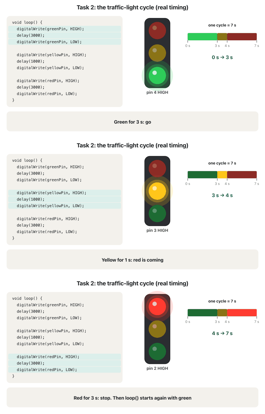
Task 2 changes only the order of the three blocks in loop(): green, then yellow, then red.
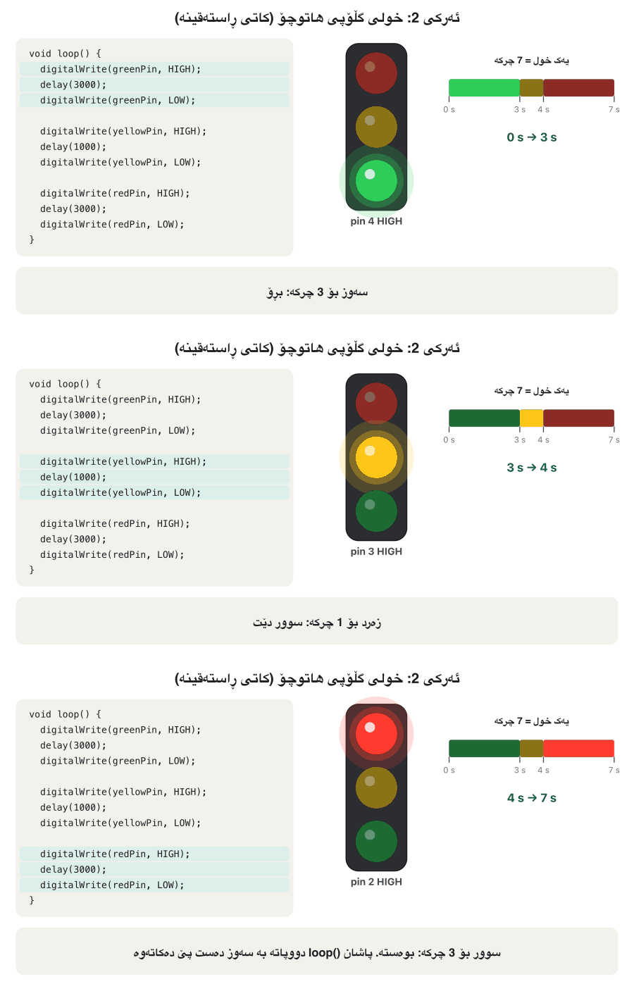
ئەرکی 2 تەنیا ڕیزبەندیی سێ بلۆکەکەی ناو loop() دەگۆڕێت: سەوز، پاشان زەرد، پاشان سوور.
// Task 2: a traffic light in the right order
const int redPin = 2;
const int yellowPin = 3;
const int greenPin = 4;

void setup() {
  pinMode(redPin, OUTPUT);
  pinMode(yellowPin, OUTPUT);
  pinMode(greenPin, OUTPUT);
}

void loop() {
  digitalWrite(greenPin, HIGH);   // green: go (3 s)
  delay(3000);
  digitalWrite(greenPin, LOW);

  digitalWrite(yellowPin, HIGH);  // yellow: red is coming (1 s)
  delay(1000);
  digitalWrite(yellowPin, LOW);

  digitalWrite(redPin, HIGH);     // red: stop (3 s)
  delay(3000);
  digitalWrite(redPin, LOW);
}0 ms pin 4 = HIGH green on 3000 ms pin 4 = LOW green off 3000 ms pin 3 = HIGH yellow on 4000 ms pin 3 = LOW yellow off 4000 ms pin 2 = HIGH red on 7000 ms pin 2 = LOW red off 7000 ms pin 4 = HIGH green on
From the pin events of the CêIT Arduino checker; this sketch prints nothing to the Serial Monitor.
لە ڕووداوەکانی پینەکانی پشکنەری Arduinoـی CêITـەوە وەرگیراوە؛ ئەم هیچ لە چاپ ناکات.
Common mistakesهەڵە باوەکان
| Mistakeهەڵە | Betterباشتر |
|---|---|
| The LED is in backwards and stays dark. پێچەوانە دانراوە و تاریک دەمێنێتەوە. | Long leg (anode) towards the pin, short leg (cathode) to GND.قاچی درێژ () بەرەو پین، قاچی کورت () بۆ GND. |
| No resistor: the LED and the pin are overloaded.بێ : و پینەکە زیاد لە توانا بار دەکرێن. | Always put a resistor in series: 330 Ω (UNO R3), 470 Ω (UNO R4), 220 Ω (MKR WAN 1310).هەمیشە بە زنجیرە دابنێ: 330 Ω (UNO R3)، 470 Ω (UNO R4)، 220 Ω (MKR WAN 1310). |
| A 220 Ω resistor on an UNO R4 (about 13.6 mA). 220 Ω لەسەر UNO R4 (نزیکەی 13.6 mA). | Stay below 8 mA per pin: use 470 Ω.لە خوار 8 mA بۆ هەر پینێک بمێنەرەوە: 470 Ω بەکار بهێنە. |
| pinMode() is missing: the LED glows dimly.pinMode() نییە: کز دادەگیرسێت. | Write pinMode(pin, OUTPUT) in setup().pinMode(pin, OUTPUT) لە setup()ـدا بنووسە. |
| Both legs of a part in the same 5-hole column.هەردوو قاچی پارچەیەک لە هەمان ستوونی 5 کونیدا. | A column is one connection: put the legs in different columns (The breadboard).ستوونێک یەک پەیوەندییە: قاچەکان لە ستوونی جیاوازدا دابنێ (بریدبۆرد). |
| The GND wire is forgotten.وایەری GND لەبیر کراوە. | Every circuit needs the way back: a wire from the blue rail to GND.هەموو ڕێگای گەڕانەوەی پێویستە: وایەرێک لە هێڵی شینەوە بۆ GND. |
| The LED is wired to the 5V pin and never goes off. بە پینی 5Vـەوە بەستراوە و هەرگیز ناکوژێتەوە. | Wire it from a digital pin such as pin 2, so the sketch can switch it.لە وەک پینی 2ـەوە بیبەستە، بۆ ئەوەی بتوانێت بیگۆڕێت. |
| The traffic light goes red → yellow → green.گڵۆپی هاتوچۆکە سوور ← زەرد ← سەوز دەگۆڕێت. | Green → yellow → red: yellow warns that red is coming.سەوز ← زەرد ← سوور: زەرد ئاگادار دەکاتەوە کە سوور دێت. |
Exercisesڕاهێنانەکان
Make the LED on pin 2 signal SOS: three short flashes (dots), three long ones (dashes) and three short ones, run together, then a pause. One Morse unit is 200 ms: a dot lasts 1 unit, a dash 3 units, the gap between flashes 1 unit and the pause between words 7 units. (SOS is sent as one signal, without the gaps between letters.) Where dots, dashes and SOS come from: Dots and dashes.
سەر پینی 2 وا لێ بکە SOS بنێرێت: سێ ترووسکەی کورت (خاڵ)، سێ درێژ (هێڵ) و سێ کورت، بە دوای یەکدا، پاشان وەستانێک. یەک یەکەی 200 msـە: خاڵ 1 یەکە دەخایەنێت، هێڵ 3 یەکە، بۆشایی نێوان ترووسکەکان 1 یەکە و وەستانی نێوان وشەکان 7 یەکە. (SOS وەک یەک دەنێردرێت، بێ بۆشایی نێوان پیتەکان.) خاڵ، هێڵ و SOS لە کوێوە هاتوون: خاڵ و هێڵ.
Hintئاماژە
Write a small function that flashes for a given time, and call it in three for loops.
بچووک بنووسە کە بۆ کاتێکی دیاریکراو دەترووکێت و لە سێ بانگی بکە.
Show answerوەڵامەکە پیشان بدە
// SOS in Morse code on pin 2: . . . - - - . . . sent as one signal
const int ledPin = 2;
const int unit = 200;               // one Morse unit, in ms

void flash(int length) {            // LED on for 'length' ms, then a 1-unit gap
  digitalWrite(ledPin, HIGH);
  delay(length);
  digitalWrite(ledPin, LOW);
  delay(unit);
}

void setup() {
  pinMode(ledPin, OUTPUT);
}

void loop() {
  for (int i = 0; i < 3; i++) {     // three dots
    flash(unit);
  }
  for (int i = 0; i < 3; i++) {     // three dashes
    flash(3 * unit);
  }
  for (int i = 0; i < 3; i++) {     // three dots
    flash(unit);
  }
  delay(6 * unit);                  // pause between words: 7 units in all
}0 ms pin 2 = HIGH LED on 200 ms pin 2 = LOW LED off 400 ms pin 2 = HIGH LED on 600 ms pin 2 = LOW LED off 800 ms pin 2 = HIGH LED on 1000 ms pin 2 = LOW LED off 1200 ms pin 2 = HIGH LED on 1800 ms pin 2 = LOW LED off 2000 ms pin 2 = HIGH LED on 2600 ms pin 2 = LOW LED off 2800 ms pin 2 = HIGH LED on 3400 ms pin 2 = LOW LED off 3600 ms pin 2 = HIGH LED on 3800 ms pin 2 = LOW LED off 4000 ms pin 2 = HIGH LED on 4200 ms pin 2 = LOW LED off 4400 ms pin 2 = HIGH LED on 4600 ms pin 2 = LOW LED off 6000 ms pin 2 = HIGH LED on 6200 ms pin 2 = LOW LED off
The whole SOS with its pause takes 6000 ms and then starts again (CêIT checker).
هەموو SOSـەکە لەگەڵ وەستانەکەی 6000 ms دەخایەنێت و پاشان دووپاتە دەست پێ دەکاتەوە (پشکنەری CêIT).
Explain the codeڕوونکردنەوەی کۆدەکە
- Lineدێڕی 5-10
flash(): LED on for the given time, then a one-unit gap.
flash(): بۆ کاتی دیاریکراو هەڵدەبێت، پاشان بۆشاییەکی یەک یەکەیی.
- Lineدێڕی 17-19
Three dots, using a for loop.
سێ خاڵ، بە .
A blue LED needs about 3.0 V. Which resistor would you use on a 5 V UNO R3 for about 10 mA, and what current flows then? Would the same LED work well on an MKR WAN 1310 (3.3 V)?
شین نزیکەی 3.0 Vـی پێویستە. لەسەر UNO R3ـی 5 V بۆ نزیکەی 10 mA کام بەکار دەهێنیت و ئینجا چ دەڕوات؟ ئایا هەمان لەسەر MKR WAN 1310 (3.3 V) باش کار دەکات؟
Show answerوەڵامەکە پیشان بدە
On the MKR WAN 1310 only is left for the resistor: with 220 Ω that is about 1.4 mA, so the LED is very dim. Use a red or yellow LED there.
لەسەر MKR WAN 1310 تەنیا بۆ دەمێنێتەوە: بە 220 Ω ئەمە نزیکەی 1.4 mAـە، بۆیە زۆر کزە. لەوێ سوور یان زەرد بەکار بهێنە.
Add a green "walk" LED for people on pin 5. It must be on only while the cars have red, and it should go off one second before the cars get green again.
سەوزی «پیاسە» بۆ خەڵک لەسەر پینی 5 زیاد بکە. دەبێت تەنیا ئەو کاتە هەڵکراو بێت کە ئۆتۆمبێلەکان سووریان هەیە و یەک چرکە پێش ئەوەی ئۆتۆمبێلەکان دووپاتە سەوز وەربگرن بکوژێتەوە.
Hintئاماژە
Split the red delay(3000) into two parts.
delay(3000)ـی سوورەکە بکە بە دوو بەش.
Show answerوەڵامەکە پیشان بدە
// A traffic light with a pedestrian "walk" light
const int redPin = 2;
const int yellowPin = 3;
const int greenPin = 4;
const int walkPin = 5;              // green "walk" light for people

void setup() {
  pinMode(redPin, OUTPUT);
  pinMode(yellowPin, OUTPUT);
  pinMode(greenPin, OUTPUT);
  pinMode(walkPin, OUTPUT);
}

void loop() {
  digitalWrite(greenPin, HIGH);     // cars go, people wait
  delay(3000);
  digitalWrite(greenPin, LOW);

  digitalWrite(yellowPin, HIGH);    // red is coming
  delay(1000);
  digitalWrite(yellowPin, LOW);

  digitalWrite(redPin, HIGH);       // cars stop ...
  digitalWrite(walkPin, HIGH);      // ... people walk
  delay(2000);
  digitalWrite(walkPin, LOW);       // walk ends 1 s before the cars move
  delay(1000);
  digitalWrite(redPin, LOW);
}0 ms pin 4 = HIGH green on 3000 ms pin 4 = LOW green off 3000 ms pin 3 = HIGH yellow on 4000 ms pin 3 = LOW yellow off 4000 ms pin 2 = HIGH red on 4000 ms pin 5 = HIGH walk on 6000 ms pin 5 = LOW walk off 7000 ms pin 2 = LOW red off 7000 ms pin 4 = HIGH green on
From the pin events of the CêIT Arduino checker; this sketch prints nothing to the Serial Monitor.
لە ڕووداوەکانی پینەکانی پشکنەری Arduinoـی CêITـەوە وەرگیراوە؛ ئەم هیچ لە چاپ ناکات.
Summaryپوختە
- Current needs a complete loop: output pin → resistor → LED → GND. GND is the 0 V reference and the way back.
- An LED works one way: long leg = anode (+), short leg and flat edge = cathode (−).
- Choose the resistor with within the pin's limit: 330 Ω (UNO R3), 470 Ω (UNO R4), 220 Ω (MKR WAN 1310).
- pinMode(pin, OUTPUT) in setup(); then digitalWrite(pin, HIGH or LOW) switches the pin like a wall switch.
- Name pins once with const int; delay() blocks the whole sketch, so busy sketches use millis().
- A traffic light goes green → yellow → red; here 3 s, 1 s and 3 s, a 7-second cycle.
- پێویستی بە سووڕێکی تەواوە: پینی ← ← ← پینی GND. GND خاڵی سەرچاوەی 0 Vـە و ڕێگای گەڕانەوەیە.
- بە یەک ئاراستە کار دەکات: قاچی درێژ = (+)، قاچی کورت و لێواری تەخت = (−).
- بە لە ناو سنووری پینەکەدا هەڵبژێرە: 330 Ω (UNO R3)، 470 Ω (UNO R4)، 220 Ω (MKR WAN 1310).
- pinMode(pin, OUTPUT) لە setup()ـدا؛ پاشان digitalWrite(pin, HIGH یان LOW) پینەکە وەک دیوار دەگۆڕێت.
- پینەکان یەک جار بە const int ناو ببە؛ delay() هەموو ڕادەگرێت، بۆیە قەرەباڵغ millis() بەکار دەهێنن.
- گڵۆپی هاتوچۆ سەوز ← زەرد ← سوور دەگۆڕێت؛ لێرەدا 3 چرکە، 1 چرکە و 3 چرکە، خولێکی 7 چرکەیی.
Why does every LED need a resistor?بۆچی هەموو LEDـێک پێویستی بە بەرگر هەیە؟
Above its on-voltage an LED's current rises very fast; the resistor sets a safe current for the LED and the pin.
لە سەرووی داگیرسانەوە زۆر خێرا زیاد دەکات؛ سەلامەت بۆ و پینەکە دیاری دەکات.
What happens if you forget pinMode(pin, OUTPUT)?ئەگەر pinMode(pin, OUTPUT) لەبیر بکەیت چی ڕوو دەدات؟
digitalWrite(HIGH) only turns on the weak internal pull-up, so the LED glows dimly.
digitalWrite(HIGH) تەنیا لاوازی ناوخۆیی هەڵدەکات، بۆیە کز دادەگیرسێت.
What is wrong with red → yellow → green?سوور ← زەرد ← سەوز چی هەڵەیە؟
Yellow warns that red is coming, so it must come between green and red.
زەرد ئاگادار دەکاتەوە کە سوور دێت، بۆیە دەبێت لە نێوان سەوز و سووردا بێت.
Lesson complete!وانەکە تەواو بوو!
Well done. Review the key terms, then go on to the next lesson.دەستخۆش. سەیرێکی زاراوە سەرەکییەکان بکەرەوە، پاشان بڕۆ بۆ وانەی داهاتوو.
Key termsزاراوە سەرەکییەکان
Lab: Talking to the Board with the Serial Monitorتاقیگە: قسەکردن لەگەڵ بۆرد بە Serial Monitor
Related lecturesوانە پەیوەندیدارەکان
- Lab: Talking to the Board with the Serial Monitorتاقیگە: قسەکردن لەگەڵ بۆرد بە Serial Monitor
- Lab: Buttons, INPUT_PULLUP and Debouncingتاقیگە: دوگمەکانی پەستان، INPUT_PULLUP و لابردنی هەڵبەزینەوە
- Lab: Dimming with PWM and Beeping with tone()تاقیگە: کزکردن بە PWM و بیپ بە tone()
- Electricity Basics: Voltage, Current and Resistanceبنەماکانی کارەبا: ڤۆڵتیە، تەزوو و بەرگری
- Components and Instruments on the Lab Benchپارچە و ئامێرەکانی سەر مێزی تاقیگە
- Analog and Digital Signalsسیگناڵەکانی ئەنالۆگ و دیجیتاڵ
- Variables, Names and Constantsگۆڕاوەکان، ناوەکان و نەگۆڕەکان
- Actuators: DC Motors, Encoders and Servosجووڵێنەرەکان: ماتۆڕەکانی DC، کۆدکەرەکانی هەنگاوبەهەنگاو و ماتۆڕەکانی سێرڤۆ
References and further readingسەرچاوەکان و خوێندنەوەی زیاتر
- Arduino reference: pinMode() (INPUT, OUTPUT, INPUT_PULLUP)
- Arduino reference: digitalWrite() (5 V or 3.3 V for HIGH; a dim LED without pinMode OUTPUT)
- Arduino reference: delay() (no other reading or pin manipulation during the delay)
- Arduino built-in examples: Blink
- Arduino UNO R4 Minima datasheet ABX00080, §9.3 Pin current (GPIO up to 8 mA)
- Arduino docs: UNO R3 tech specs (DC current per I/O pin 20 mA)
- Arduino docs: MKR WAN 1310 tech specs (3.3 V I/O, 7 mA per pin)
- Wikipedia: Traffic light (usual sequence green, amber, red; UK red and amber before green)
- Wikipedia: Morse code (dot 1 unit, dash 3 units, gaps of 1, 3 and 7 units)
This lecture is a first edition. The Kurdish text and terminology are waiting for review by Kurdish IT teachers.ئەم وانەیە چاپی یەکەمە. دەقە کوردییەکە و زاراوەکانی چاوەڕێی پێداچوونەوەی مامۆستایانی کوردی بواری IT ن.