Chapterبەش 6 · Lectureوانە 6.6
Building Gates from Transistorsدروستکردنی گەیتەکان لە ترانزیستۆرەکانەوە
What is inside a logic gate: the transistor as a switch controlled by a small base current (with a tap analogy); NPN and PNP; the course author's simulator circuits for AND (series) and OR (parallel), with an animation; NOT, NAND and NOR that pull the output down, redrawn with values that are safe for real parts; why real gates take the output from the collector (RTL); and the logic families from diode logic to today's CMOS.
چی لە ناو : وەک کە بە بچووکی کۆنترۆڵ دەکرێت (بە نموونەی شێری ئاو)؛ NPN و PNP؛ خاوەنی کۆرسەکە بۆ AND () و OR ()، بە ئەنیمەیشنێک؛ NOT، NAND و NOR کە دادەبەزێنن، دووبارە کێشراون بە نرخی بێ مەترسی بۆ پارچەی ڕاستەقینە؛ بۆچی لە وەردەگرن (RTL)؛ و لە لۆجیکی تا CMOSـی ئەمڕۆ.
What you will learnچی فێر دەبیت
- Explain how a small base current switches a transistor fully off or fully on, and name its three terminals.
- Trace transistor circuits for AND, OR, NOT, NAND and NOR for every input combination.
- Choose safe base and LED resistor values and spot unsafe ones.
- Explain why NAND and NOR are the natural gates of RTL, and why CMOS is used today.
- ڕوون بکەیتەوە چۆن بچووکی بە تەواوی دەکوژێنێتەوە یان هەڵی دەکات و سێ لاقەکەی ناو ببەیت.
- AND، OR، NOT، NAND و NOR بۆ هەموو تێکەڵەیەکی بەدوادا بچیت.
- نرخی بێ مەترسی بۆ و LED هەڵبژێریت و نرخە مەترسیدارەکان بناسیتەوە.
- ڕوون بکەیتەوە بۆچی NAND و NOR RTLـن و بۆچی ئەمڕۆ CMOS بەکار دێت.
What is inside a gate?چی لە ناو گەیتێکدایە؟
So far every gate was a symbol with a truth table. Gates are real chips said that inside a chip each gate is “a few transistors”. This lesson opens the box: with the course author's own simulator circuits it shows how one, two or more transistors make NOT, AND, OR, NAND and NOR — and why the chips of today are built the way they are.
تا ئێستا هەر بوو لەگەڵ . وانەی گەیتەکان چیپی ڕاستەقینەن گوتی لە ناو هەر «چەند ». ئەم وانەیە سندووقەکە دەکاتەوە: بە خودی خاوەنی کۆرسەکە پیشان دەدات چۆن یەک، دوو یان زیاتر NOT، AND، OR، NAND و NOR دروست دەکەن — و بۆچی ئەمڕۆ بەم شێوەیە دروست دەکرێن.
The transistor is the single part that drove the electronics revolution. Once engineers learned to make many of them on one piece of silicon, the integrated circuit was born, and with it microprocessors with billions of transistors (A whole CPU on one chip).
ئەو تاکە پارچەیەیە کە شۆڕشی ئەلیکترۆنیاتی هێنایە ئاراوە. کاتێک ئەندازیاران فێر بوون زۆریان لەسەر یەک پارچە سیلیکۆن دروست بکەن، لە دایک بوو و لەگەڵیدا پرۆسێسەرەکان بە ملیارەها (CPUـێکی تەواو لەسەر یەک چیپ).
A transistor is a switch you control with a small currentترانزیستۆر سویچێکە کە بە تەزوویەکی بچووک کۆنترۆڵی دەکەیت
A transistor is a three-terminal semiconductor part that controls current and can act as an electronic switch with no moving parts. The common kind in logic labs is the bipolar junction transistor (BJT), whose terminals are the base (B), the collector (C) and the emitter (E). A small current flowing into the base and out of the emitter lets a much larger current flow from the collector to the emitter. No base current, no collector current.
پارچەیەکی سێ لاقییە کە کۆنترۆڵ دەکات و دەتوانێت وەک ئەلیکترۆنی بێ بەشی جووڵاو کار بکات. جۆرە باوەکەی تاقیگەکانی لۆجیک دوو جەمسەری (BJT)ـە کە لاقەکانی (B)، (C) و (E)ـن. بچووک کە دەچێتە ناو و لە دەردەچێت ڕێگە دەدات زۆر گەورەتر لە بۆ بڕوات. نەبێت، نابێت.
Think of the tap under the water tank on the roof. The water waiting in the pipe is the collector's supply; the water that pours out is the emitter's current. A small twist of the handle — the base current — decides whether a big stream flows or none at all.
بیر لە شێرەکەی ژێر تانکی ئاوی سەربان بکەرەوە. ئەو ئاوەی لە بۆرییەکەدا چاوەڕێ دەکات سەرچاوەی ؛ ئەو ئاوەی دەڕژێت . سووڕاندنێکی بچووکی دەسکەکە — — بڕیار دەدات ئایا ڕووبارێکی گەورە بڕوات یان هیچ.
Where the analogy stops workingسنووری ئەم نموونەیە
A real handle stays where you leave it; a transistor stays on only while base current keeps flowing. And in a logic gate the tap is never left half open: it is either fully off or fully on.
دەسکێکی ڕاستەقینە لە هەر شوێنێک جێی بهێڵیت دەمێنێتەوە؛ تەنها تا ئەو کاتە هەڵکراو دەمێنێت کە بەردەوام بێت. هەروەها لە شێرەکە هەرگیز نیوە کراوە جێ ناهێڵرێت: یان بە تەواوی کوژاوەیە یان بە تەواوی هەڵکراو.
A transistor is an electronic switch: a small control current lets a bigger current flow, and chains of them make gates.
ئەلیکترۆنییە: بچووکی کۆنترۆڵ ڕێگە دەدات گەورەتر بڕوات و زنجیرەیەک لەوان دروست دەکەن.
Chapter 'What is a Transistor' (2:32-5:47); simple animation of the switch idea.
بەشی What is a Transistor (2:32 تا 5:47)؛ سادە بۆ بیرۆکەی .
A transistor is a switch you control with a small currentترانزیستۆر سویچێکە کە بە تەزوویەکی بچووک کۆنترۆڵی دەکەیت
NPN and PNP, and the three legsNPN و PNP و سێ لاقەکە
Bipolar transistors come in two types, NPN and PNP; most switching circuits, including every circuit in this lesson, use NPN. In the symbol the arrow is on the emitter and shows the direction of conventional current: out of an NPN, into a PNP.
دوو جەمسەری دوو جۆرن، NPN و PNP؛ زۆربەی سویچکردن، لەوانە هەموو ئەم وانەیە، NPN بەکار دەهێنن. لە تیرەکە لەسەر و ئاراستەی ڕێککەوتووی پیشان دەدات: لە NPNـدا بەرەو دەرەوە، لە PNPـدا بەرەو ژوورەوە.
The course author's circuits use the 2N2222A, a common small NPN transistor: it can switch up to about 600 mA at up to 40 V, far more than an LED needs.
خاوەنی کۆرسەکە 2N2222A بەکار دەهێنن، NPNـی بچووکی باو: دەتوانێت تا نزیکەی 600 mA بە تا 40 V بگۆڕێت، زۆر زیاتر لەوەی پێویستی پێیەتی.
A transistor is a switch you control with a small currentترانزیستۆر سویچێکە کە بە تەزوویەکی بچووک کۆنترۆڵی دەکەیت
Fully off or fully onبە تەواوی کوژاوە یان بە تەواوی هەڵکراو
A logic circuit uses a transistor in only two states. With no base current it is off (in cut-off): the collector–emitter path is like an open switch. With enough base current it is fully on (saturated): the path is like a closed switch with only about 0.2 V across it. A base needs about 0.7 V before current flows into it, so it is always fed through a base resistor that sets the current.
تەنها لە دوو دۆخدا بەکار دەهێنێت. بە بێ کوژاوەیە: ڕێگای نێوان و وەک کراوەیە. بە بەس بە تەواوی هەڵکراوە: ڕێگاکە وەک داخراوە و تەنها نزیکەی 0.2 V لە نێوان دوو سەریدایە. پێویستی بە نزیکەی 0.7 V هەیە پێش ئەوەی بچێتە ناوی، بۆیە هەمیشە بە ناو وزەی پێ دەدرێت کە دیاری دەکات.
How much base current is enough? A transistor multiplies its base current by its gain (hFE), usually 50 to 400. To switch 10 mA with a gain of 100, the base needs at least ; designers give it several times more to be sure. From 9 V through a 10 kΩ base resistor, the base gets — plenty.
چەند بەسە؟ جارانی قازانجەکەی (gain، hFE) دەکات، کە زۆرجار 50 تا 400ـە. بۆ گۆڕینی 10 mA بە قازانجی 100، لانیکەم پێویستی بە هەیە؛ دیزاینەران بۆ دڵنیایی چەند هێندە زیاتری دەدەنێ. لە 9 Vـەوە بە 10 kΩـدا، وەردەگرێت — زۆر بەسە.
AND: two transistors in seriesAND: دوو ترانزیستۆر بە بەستنی زنجیرەیی
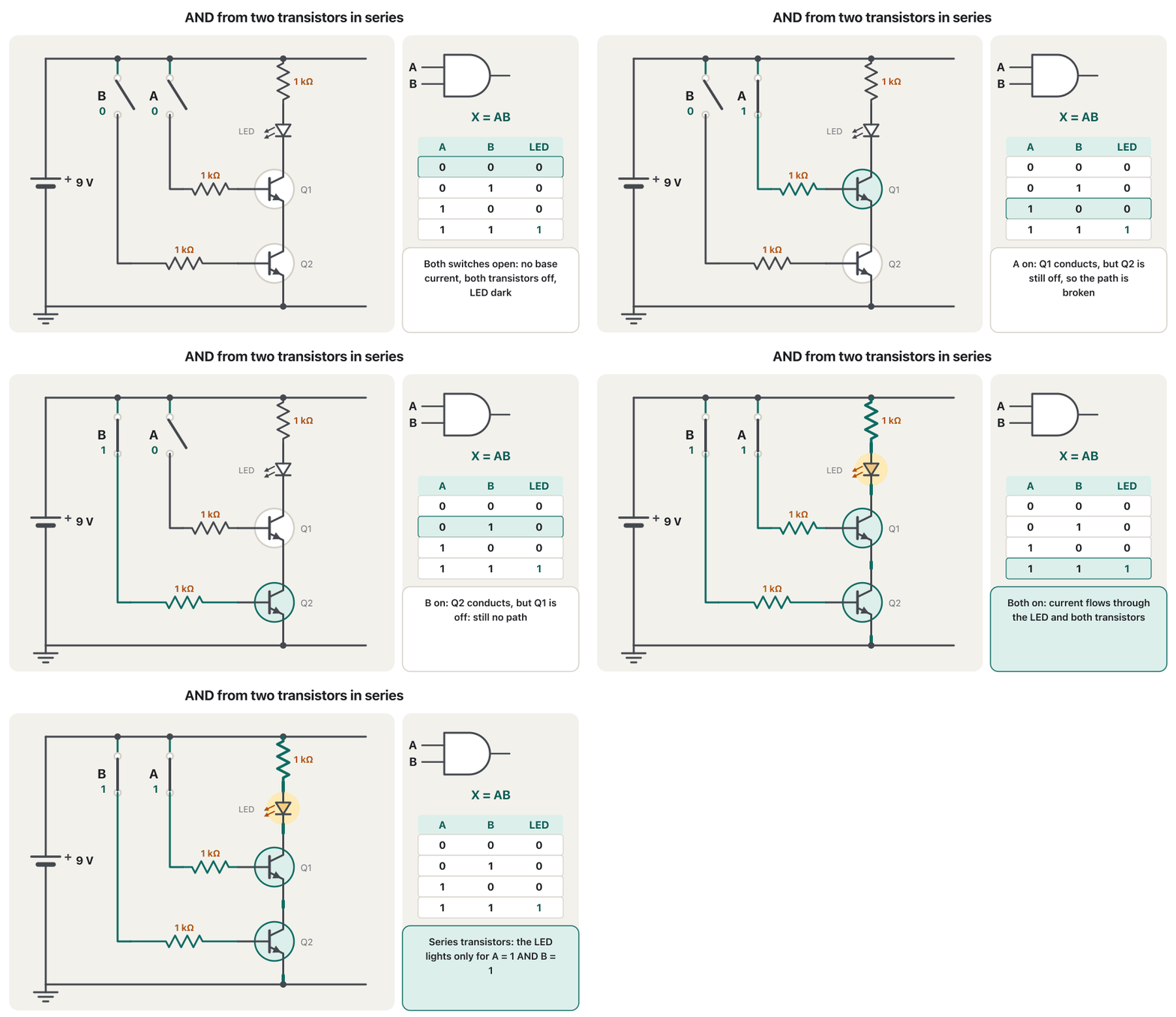
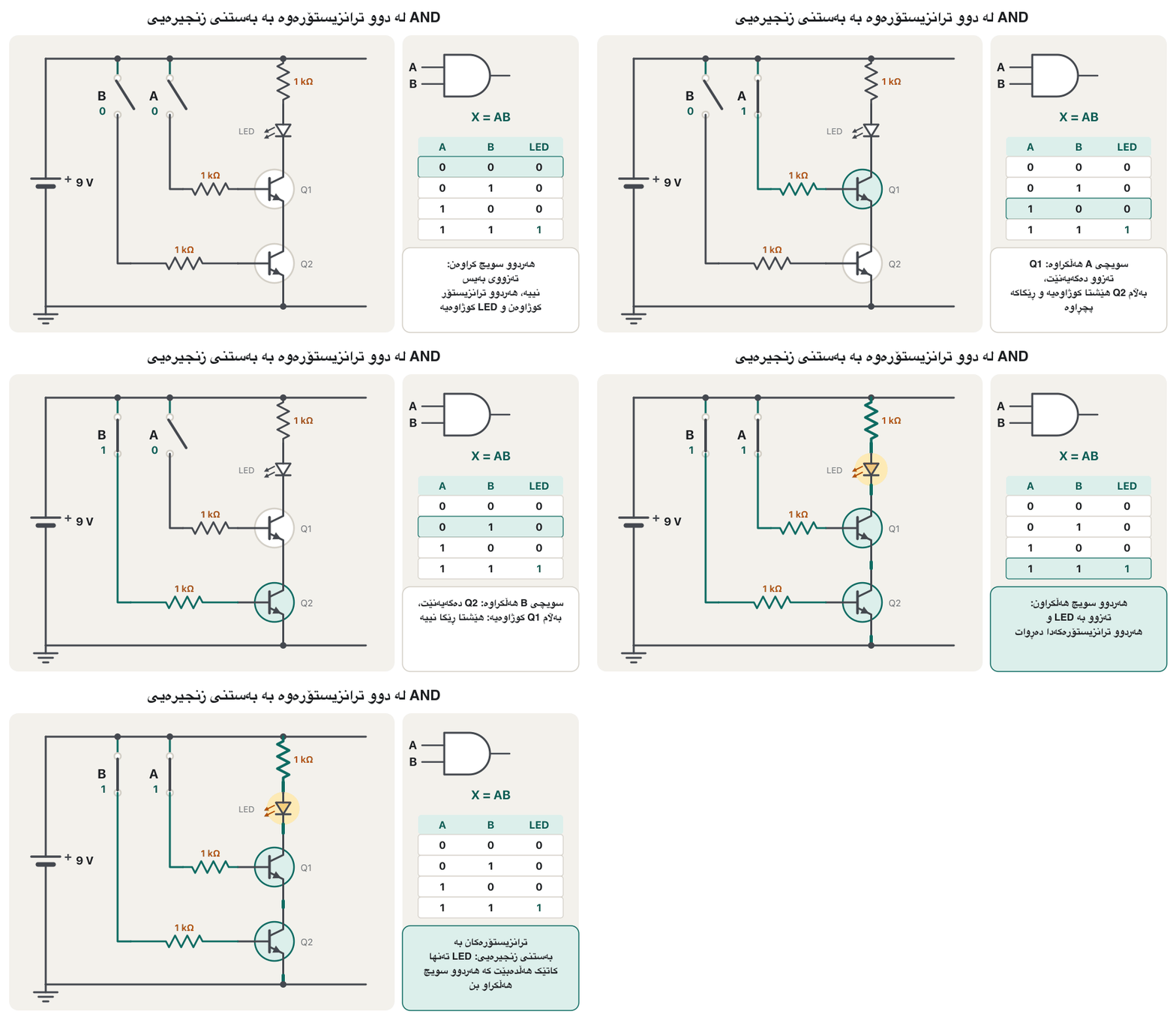
The course author built this AND gate in Multisim. A 9 V battery feeds a DIP switch S2 with two switches. Each switch sends current through a 1 kΩ base resistor (R1, R2) into one 2N2222A transistor (Q1, Q2). The two transistors sit in series between the LED (with its 1 kΩ resistor R3) and ground. The LED can light only if both transistors conduct — exactly like two switches in series.
خاوەنی کۆرسەکە ئەم لە Multisimـدا دروست کرد. پاترییەکی 9 V وزە دەداتە DIPـی دوو دانەیی (S2). هەر بە 1 kΩـدا (R1، R2) دەنێرێتە ناو 2N2222A (Q1، Q2). دوو بە لە نێوان (لەگەڵ R3، 1 kΩ) و دانراون. تەنها کاتێک هەڵدەبێت کە هەردوو بگەیەنن — ڕێک وەک دوو سویچ بە دوای یەکدا.
With both switches on, the current flows from +9 V through R3 and the LED, then through Q1 and Q2 to ground: about (2 V for the LED and about 0.2 V for each saturated transistor). If either switch is off, its transistor is an open switch and the path is broken.
کاتێک هەردوو هەڵکراون، لە +9 Vـەوە بە R3 و دەڕوات، پاشان بە Q1 و Q2ـدا بۆ : نزیکەی (2 V بۆ و نزیکەی 0.2 V بۆ هەر تەواو هەڵکراو). ئەگەر هەر کوژاوە بێت، وەک کراوەیە و ڕێگاکە دەپچڕێت.
AND: two transistors in seriesAND: دوو ترانزیستۆر بە بەستنی زنجیرەیی
Watch the AND circuitسەیری سووڕی AND بکە
The animation goes through the four input combinations. Watch which transistors switch on and when the current finally has a complete path.
ئەنیمەیشنەکە بە چوار تێکەڵەی تێدەپەڕێت. سەیر بکە کام هەڵدەبن و کەی لە کۆتاییدا ڕێگایەکی تەواوی دەبێت.
OR: two transistors in parallelOR: دوو ترانزیستۆر بە بەستنی هاوتەریب
For OR the course author put the two transistors (Q3, Q4) in parallel: both collectors join below the LED (with its 1 kΩ resistor R6) and both emitters go to ground. Either transistor alone gives the current a path, so the LED lights when A or B (or both) is on — like two switches in parallel.
بۆ OR خاوەنی کۆرسەکە دوو (Q3، Q4) بە دانا: هەردوو لە ژێر (لەگەڵ R6، 1 kΩ) بەیەک دەگەن و هەردوو دەچنە سەر . هەر بە تەنها ڕێگایەک بە دەدات، بۆیە هەڵدەبێت کاتێک A یان B (یان هەردووکیان) هەڵکراو بێت — وەک دوو سویچی هاوتەریب.
NOT: one transistor pulls the output downNOT: یەک ترانزیستۆر دەرخستە دادەبەزێنێت
For NOT the LED is not in the transistor's path. A resistor joins +V to the collector, and the LED (with its own resistor) hangs from that collector point to ground. The transistor sits between the collector point and ground, like a switch across the LED:
بۆ NOT لە ڕێگای نییە. +V بە دەبەستێت و (لەگەڵ خۆی) لەو خاڵەی بۆ دادەنرێت. لە نێوان خاڵی و ، وەک بە دوو سەری :
- Switch A open (input 0): no base current, so the transistor is off. Current flows from +V through the collector resistor into the LED: the LED is on (output 1).
- Switch A closed (input 1): base current flows, the transistor turns fully on and pulls the collector down to about 0.2 V. That is far below the LED's 2 V, so the LED goes dark (output 0).
- A کراوە ( 0): نییە، بۆیە کوژاوەیە. لە +Vـەوە بە دەچێتە ناو : هەڵکراوە ( 1).
- A داخراو ( 1): دەڕوات، بە تەواوی هەڵدەبێت و دادەبەزێنێت بۆ نزیکەی 0.2 V. ئەمە زۆر لە خوار 2 Vـی ، بۆیە دەکوژێتەوە ( 0).
One NPN transistor as an inverter: input LOW gives output HIGH, input HIGH pulls the output LOW, with resistor values worked out.
یەک NPN وەک پێچەوانەکەر: LOW HIGH دەدات و HIGH دادەبەزێنێت بۆ LOW، لەگەڵ هەژمارکردنی نرخی .
Chapter 'Transistor as inverter' (11:16-end).
بەشی Transistor as inverter (لە 11:16ـەوە تا کۆتایی).
NOT: one transistor pulls the output downNOT: یەک ترانزیستۆر دەرخستە دادەبەزێنێت
Values that are safe for real partsنرخی بێ مەترسی بۆ پارچەی ڕاستەقینە
NAND and NOR: transistors that pull the output downNAND و NOR: ئەو ترانزیستۆرانەی دەرخستە دادەبەزێنن
NAND and NOR use the NOT idea with two transistors. The output is the collector point, joined to +V by a resistor. The transistors form a path from that point to ground: when the path conducts, the output is pulled LOW and the LED goes dark.
NAND و NOR بیرۆکەی NOT بە دوو بەکار دەهێنن. خاڵی کە بە بە +Vـەوە بەستراوە. ڕێگایەک لەو خاڵەوە بۆ پێک دەهێنن: کاتێک ڕێگاکە دەگەیەنێت، LOW دەکرێت و دەکوژێتەوە.
| Gate | Pull-down transistors دابەزێنەر | Output LOW when … LOWـە کاتێک … |
|---|---|---|
| NOT | oneیەک | |
| NAND | two in seriesدوو بە | and و |
| NOR | two in parallelدوو بە | or یان |
NAND and NOR: transistors that pull the output downNAND و NOR: ئەو ترانزیستۆرانەی دەرخستە دادەبەزێنن
NAND: the series pairNAND: جووتە زنجیرەییەکە
In NAND the two transistors are stacked in series between the output and ground. Only when both switches are on is there a path to ground, so the output (and the LED) goes LOW only for — the AND circuit with its output turned upside down.
لە NANDـدا دوو بە لە نێوان و لەسەر یەک دانراون. تەنها کاتێک هەردوو هەڵکراو بن ڕێگایەک بۆ هەیە، بۆیە (و ) تەنها بۆ LOW دەبێت — AND بە پێچەوانەکراوەوە.
NAND and NOR: transistors that pull the output downNAND و NOR: ئەو ترانزیستۆرانەی دەرخستە دادەبەزێنن
NOR: the parallel pairNOR: جووتە هاوتەریبەکە
The author's gate sheet also lists NOR, and the practical's example files include a NOR gate built from transistors. Put the two pull-down transistors in parallel: either one conducting pulls the output LOW. The LED is on only when — the OR circuit, inverted.
پەڕەی خاوەنی کۆرسەکە NORـیش دەژمێرێت و فایلە نموونەییەکانی بەشی پراکتیکی دروستکراو لە لەخۆ دەگرن. دوو دابەزێنەرەکە بە دابنێ: هەر یەکێکیان بگەیەنێت LOW دەکات. تەنها کاتێک هەڵکراوە کە — OR بە پێچەوانەکراوی.
Why real gates take the output from the collectorبۆچی گەیتە ڕاستەقینەکان دەرخستە لە کۆلێکتەرەوە وەردەگرن
The AND and OR circuits above light an LED that sits inside the transistor path. That is fine for a demonstration, but a real gate's output must be a voltage — HIGH or LOW — that the next gate's input can read. So real transistor gates take their output from the collector, with a resistor (a pull-up) to +V, exactly like the NOT, NAND and NOR circuits. This family of gates is called resistor–transistor logic (RTL).
AND و ORـی سەرەوە LEDـێک هەڵدەکەن کە لە ناو ڕێگای . ئەمە بۆ پیشاندان باشە، بەڵام ڕاستەقینە دەبێت بێت — HIGH یان LOW — کە دواتر بتوانێت بیخوێنێتەوە. بۆیە ڕاستەقینە لە وەردەگرن، بە (بەرزکەرەوە) بۆ +V، ڕێک وەک NOT، NAND و NOR. ئەم خێزانە لە پێی دەوترێت لۆجیکی بەرگر–ترانزیستۆر (RTL).
Look at what comes out naturally: one transistor gives NOT, a series pair NAND, a parallel pair NOR. A non-inverting AND or OR needs one more stage (NAND + NOT, NOR + NOT). That is why NAND and NOR are the cheapest gates to build — and why each of them alone can build every other gate (universal gates). The Apollo Guidance Computer that flew to the Moon (from 1966) was built almost entirely from integrated RTL 3-input NOR gates.
سەیری ئەوە بکە کە بە سروشتی دێتە دەرەوە: یەک NOT دەدات، جووتێکی زنجیرەیی NAND و جووتێکی هاوتەریب NOR. AND یان ORـی پێچەوانەنەکەر پێویستی بە قۆناغێکی زیاترە (NAND + NOT، NOR + NOT). بۆیە NAND و NOR هەرزانترین بۆ دروستکردن — و بۆیە هەر یەکێکیان بە تەنها دەتوانێت هەموو تر دروست بکات (گەیتە گشتگیرەکان). ڕێنمایی Apollo کە بەرەو مانگ فڕی (لە 1966ـەوە) نزیکەی هەمووی لە RTLـی سێ دروست کرابوو.
Logic families: from diodes to CMOSخێزانە لۆجیکییەکان: لە دایۆدەوە تا CMOS
Over sixty years engineers built gates in several ways. Each way is a logic family: chips of one family share a supply voltage, speed and power use, and can be connected to each other.
لە ماوەی شەست ساڵدا ئەندازیاران بە چەند شێوەیەک دروست کرد. هەر شێوەیەک : یەک خێزان ، خێرایی و وزەخواردنیان وەک یەکە و دەتوانرێت بە یەکەوە ببەسترێن.
| Familyخێزان | Built fromدروستکراو لە | Notesتێبینی |
|---|---|---|
| DL — diode logicDL — لۆجیکی | diodes and resistors و | only AND and OR, no NOT; the signal weakens at every stage (1940s, ENIAC)تەنها AND و OR، NOTـی نییە؛ لە هەر قۆناغێکدا لاواز دەبێت (ساڵانی 1940، ENIAC) |
| RTL — resistor–transistor logicRTL — لۆجیکی بەرگر–ترانزیستۆر | resistors and bipolar transistors و دوو جەمسەری | the first integrated logic family (1961); NOR is its basic gate; Apollo Guidance Computerیەکەم کە وەک دروست کرا (1961)؛ NOR بنەڕەتییەتی؛ Apollo |
| DTL — diode–transistor logicDTL — لۆجیکی دایۆد–ترانزیستۆر | diodes for the logic, a transistor to amplify بۆ لۆجیک، بۆ بەهێزکردن | 1962; better noise margin than RTL1962؛ بەرگەگرتنی باشتر لە RTL |
| TTL — transistor–transistor logicTTL — لۆجیکی ترانزیستۆر–ترانزیستۆر | bipolar transistors onlyتەنها دوو جەمسەری | the 7400 series (1964), 5 V; the classic lab chipsزنجیرەی 7400 (1964)، 5 V؛ تاقیگە |
| ECL — emitter-coupled logicECL — لۆجیکی -بەستراو | transistors that never saturate کە هەرگیز بە تەواوی هەڵناکرێن | very fast but power-hungry; for special high-speed usesزۆر خێرا بەڵام وزەخۆر؛ بۆ کاری تایبەتی خێرایی بەرز |
| CMOS — complementary MOSCMOS — MOSـی تەواوکەر | pairs of p-type and n-type MOSFETsجووتی MOSFETـی جۆری p و جۆری n | almost no current at rest; the 4000 series (1968) and 74HC; today nearly every chipلە کاتی وەستاندا نزیکەی هیچ ناخوات؛ زنجیرەی 4000 (1968) و 74HC؛ ئەمڕۆ نزیکەی هەموو |
Logic families: from diodes to CMOSخێزانە لۆجیکییەکان: لە دایۆدەوە تا CMOS
The CMOS inverter: two transistorsپێچەوانەکەری CMOS: دوو ترانزیستۆر
A CMOS inverter uses a complementary pair: a p-type transistor (PMOS) between +V and the output, and an n-type transistor (NMOS) between the output and ground. One input drives both gates. A 0 at the input turns the PMOS on and the NMOS off, so the output is connected to +V (1). A 1 turns the NMOS on and the PMOS off, so the output goes to ground (0).
پێچەوانەکەری CMOS جووتێکی تەواوکەر بەکار دەهێنێت: جۆری p (PMOS) لە نێوان +V و و جۆری n (NMOS) لە نێوان و . یەک هەردووکیان دەجووڵێنێت. 0 لە PMOS هەڵدەکات و NMOS دەکوژێنێتەوە، بۆیە بە +Vـەوە دەبەسترێت (1). 1 NMOS هەڵدەکات و PMOS دەکوژێنێتەوە، بۆیە دەچێتە سەر (0).
Because one transistor of the pair is always off, there is never a steady path from +V to ground: a CMOS gate draws current almost only while it switches. Compare the NOT circuit above, where the collector resistor wastes current whenever the transistor is on. CMOS gates follow the same pattern as before: a 2-input NAND uses 4 transistors (two in series, two in parallel), and an AND is a NAND plus an inverter, 6 transistors — so a 74HC08 with four AND gates holds 24 transistors.
لەبەر ئەوەی یەکێک لە جووتەکە هەمیشە کوژاوەیە، هەرگیز ڕێگایەکی جێگیر لە +Vـەوە بۆ نییە: CMOS نزیکەی تەنها لە کاتی گۆڕاندا دەخوات. بەراوردی بکە بە NOTـی سەرەوە، کە هەر کاتێک هەڵکراو بێت بەفیڕۆ دەدات. CMOS هەمان نەخشە دەگرنەبەر: NANDـی دوو 4 بەکار دەهێنێت (دوو بە ، دوو بە ) و AND بریتییە لە NAND و پێچەوانەکەرێک، 6 — بۆیە 74HC08 کە چوار هەیە 24 لەخۆ دەگرێت.
Inside a CMOS inverter: how PMOS and NMOS transistors switch and why one is always off, shown in 3-D animation.
ناوەوەی پێچەوانەکەرێکی CMOS: PMOS و NMOS چۆن هەڵدەبن و دەکوژێنەوە و بۆچی هەمیشە یەکێکیان کوژاوەتەوە، بە سێ ڕەهەندی.
2:12-10:45: inverter standard cell, how basic transistors work, inverter schematic.
لە 2:12 تا 10:45: خانەی ستانداردی پێچەوانەکەر، چۆن کار دەکەن و پێچەوانەکەر.
Common mistakesهەڵە باوەکان
| Mistakeهەڵە | Fixچارەسەر |
|---|---|
| Driving the base straight from the supply, with no resistor (or with 100 Ω at 12 V).جووڵاندنی ڕاستەوخۆ لە سەرچاوەکەوە بێ (یان بە 100 Ω بە 12 V). | Always use a base resistor of about 1 kΩ to 10 kΩ; a fraction of a milliampere to a few milliamperes is enough.هەمیشە نزیکەی 1 kΩ تا 10 kΩ بەکار بهێنە؛ بەشێک لە میلیئەمپێرێک تا چەند میلیئەمپێرێک بەسە. |
| Mixing up collector and emitter of an NPN.تێکەڵکردنی و NPN. | The arrow marks the emitter; it goes to ground. The collector goes to the load and +V.تیرەکە نیشان دەدات؛ دەچێتە سەر . دەچێتە لای و +V. |
| Confusing series and parallel pull-downs.تێکەڵکردنی دابەزێنەری زنجیرەیی و هاوتەریب. | Series pull-downs → NAND (all inputs needed); parallel pull-downs → NOR (any input is enough).دابەزێنەری زنجیرەیی ← NAND (هەموو پێویستن)؛ دابەزێنەری هاوتەریب ← NOR (هەر بەسە). |
| Thinking the LED circuits are finished gates.وا بیرکردنەوە کە LED . | A real gate outputs a voltage for the next gate; it takes the output from the collector. ڕاستەقینە بۆ دواتر دەدات؛ لە وەردەگرێت. |
Giving two inputs the same name (two Key = A).دانانی هەمان ناو بۆ دوو (دوو Key = A). | Each input of a gate needs its own key: A, B, C …هەر خۆی پێویستە: A، B، C … |
| “CMOS is slow.”«CMOS خاوە.» | That was the 1960s; CMOS is today's fast, low-power standard.ئەوە ساڵانی 1960 بوو؛ CMOS ستانداردی خێرا و کەمخەرجی ئەمڕۆیە. |
Exercisesڕاهێنانەکان
For the redrawn NOT circuit (12 V, 10 kΩ base, 1 kΩ collector, 1 kΩ + LED), say for and whether the transistor is on, what the output voltage roughly is, and whether the LED lights.
بۆ NOTـی دووبارە کێشراو (12 V، 10 kΩ، 1 kΩ، 1 kΩ + LED)، بۆ و بڵێ ئایا هەڵکراوە، نزیکەی چەندە و ئایا LED هەڵدەبێت.
Show answerوەڵامەکە پیشان بدە
| A | Transistor | Output | LED |
|---|---|---|---|
| 0 | offکوژاوە | about 7 V (HIGH)نزیکەی 7 V (HIGH) | on, about 5 mAهەڵکراو، نزیکەی 5 mA |
| 1 | on (saturated)هەڵکراو (تەواو) | about 0.2 V (LOW)نزیکەی 0.2 V (LOW) | offکوژاوە |
With the current along 12 V → 1 kΩ → 1 kΩ → LED is , and the output sits at .
بە ، بە ڕێگای 12 V ← 1 kΩ ← 1 kΩ ← LEDـدا دەکاتە و دەبێتە .
The original NOT circuit on the sheet used 12 V with a 100 Ω base resistor and 100 Ω + 100 Ω in the LED path. Calculate the base current (take 0.7 V for the base) and the LED current (take 2 V for the LED). Then do the same for the author's AND circuit (9 V, 1 kΩ base, 1 kΩ LED resistor, two transistors of about 0.2 V each).
NOTـی ڕەسەنی پەڕەکە 12 Vـی بە 100 Ω و 100 Ω + 100 Ω لە ڕێگای LEDـدا بەکار هێنا. (0.7 V بۆ دابنێ) و LED (2 V بۆ LED دابنێ) بژمێرە. پاشان هەمان شت بۆ ANDـی خاوەنی کۆرسەکە بکە (9 V، 1 kΩ، LEDـی 1 kΩ، دوو هەر یەکە نزیکەی 0.2 V).
Show answerوەڵامەکە پیشان بدە
The NOT values are far too high for real parts; the AND values are sensible (a smaller base current, such as 1 mA from 8.2 kΩ, would also do).
نرخەکانی NOT بۆ پارچەی ڕاستەقینە زۆر بەرزن؛ نرخەکانی AND گونجاون ( کەمتر، وەک 1 mA لە 8.2 kΩـەوە، ئەویش بەس دەبوو).
Using the pull-down idea, describe how to build (a) a 3-input NAND and (b) a 3-input NOR from NPN transistors. For each, give the only input combination(s) that make the LED (on the output) go dark.
بە بیرۆکەی دابەزێنەر، ڕوون بکەرەوە چۆن (أ) NANDـی سێ و (ب) NORـی سێ لە NPN دروست دەکەیت. بۆ هەر یەکەیان ئەو تێکەڵە یان تێکەڵانەی بنووسە کە LEDـی سەر دەکوژێننەوە.
Show answerوەڵامەکە پیشان بدە
- (a) Three transistors in series from the output to ground: the LED is dark only for (1 of the 8 rows).
- (b) Three transistors in parallel: the LED is dark whenever at least one input is 1 — in 7 of the 8 rows; it lights only for 000.
- (أ) سێ بە لە بۆ : LED تەنها بۆ کوژاوەیە (1 لە 8 ڕیز).
- (ب) سێ بە : LED هەر کاتێک لانیکەم یەک 1 بێت کوژاوەیە — لە 7 لە 8 ڕیز؛ تەنها بۆ 000 هەڵدەبێت.
(a) Two NPN transistors in series light an LED that is in their collector path. (b) Two NPN transistors in parallel pull down a collector point that feeds an LED. (c) One NPN transistor pulls down a collector point that feeds the base of a second NPN, whose collector point feeds an LED.
(أ) دوو NPN بە LEDـێک هەڵدەکەن کە لە ڕێگای . (ب) دوو NPN بە خاڵێکی دادەبەزێنن کە وزە دەداتە LEDـێک. (ج) یەک NPN خاڵێکی دادەبەزێنێت کە وزە دەداتە NPNـێکی دووەم، کە خاڵی وزە دەداتە LEDـێک.
Show answerوەڵامەکە پیشان بدە
- (a) AND.
- (b) NOR.
- (c) Two inverters in a row: a buffer, whose output equals A (as in the RTL picture).
- (أ) ئەمە .
- (ب) ئەمە .
- (ج) دوو پێچەوانەکەر لە دوای یەک: بافەر (buffer)، کە وەک A وایە (وەک وێنەی RTL).
A CMOS gate needs one PMOS and one NMOS per input, plus an extra inverter (2 transistors) for AND or OR. How many transistors are in (a) a 3-input NAND, (b) a 2-input NOR, (c) a 2-input OR, (d) the 74HC32 chip with four 2-input OR gates?
CMOS بۆ هەر PMOSـێک و NMOSـێکی پێویستە، لەگەڵ پێچەوانەکەرێکی زیادە (2 ) بۆ AND یان OR. چەند لە (أ) NANDـی سێ ، (ب) NORـی دوو ، (ج) ORـی دوو ، (د) 74HC32 بە چوار دوو هەیە؟
Show answerوەڵامەکە پیشان بدە
- (a) 6 transistors
- (b) 4 transistors
- (c) transistors
- (d) transistors
- (أ) شەش
- (ب) چوار
- (ج) ، واتە شەش
- (د) ، واتە 24
Summaryپوختە
- A bipolar transistor has a base, a collector and an emitter; a small base current switches a large collector–emitter current (NPN: arrow out on the emitter).
- In logic it is fully off or fully on; it always needs a base resistor (1 kΩ to 10 kΩ, not 100 Ω).
- Transistors in series in the LED path give AND; in parallel give OR.
- Taking the output from the collector with a pull-up resistor gives NOT (one), NAND (series pair) and NOR (parallel pair): RTL.
- Families: DL → RTL → DTL → TTL (7400) → ECL → CMOS; CMOS uses complementary pairs and almost no current at rest, and is today's standard.
- دوو جەمسەری ، و هەیە؛ بچووکی گەورەی نێوان و دەگۆڕێت (NPN: تیر بەرەو دەرەوە لەسەر ).
- لە لۆجیکدا یان بە تەواوی کوژاوەیە یان بە تەواوی هەڵکراو؛ هەمیشە پێویستی بە هەیە (1 kΩ تا 10 kΩ، نەک 100 Ω).
- بە لە ڕێگای LEDـدا AND دەدەن؛ بە OR.
- وەرگرتنی لە بە بەرزکەرەوە NOT (یەک)، NAND (جووتی زنجیرەیی) و NOR (جووتی هاوتەریب) دەدات: RTL.
- خێزانەکان: DL → RTL → DTL → TTL (7400) → ECL → CMOS؛ CMOS جووتی تەواوکەر بەکار دەهێنێت و لە کاتی وەستاندا نزیکەی هیچ ناخوات و ستانداردی ئەمڕۆیە.
Why does the NAND's LED stay lit when only one switch is on?بۆچی LEDـی NAND هەڵکراو دەمێنێتەوە کاتێک تەنها یەک سویچ هەڵکراوە؟
The pull-down transistors are in series; with one of them off there is no path to ground, so the output stays HIGH.
دابەزێنەرەکان بە ؛ کاتێک یەکێکیان کوژاوە بێت هیچ ڕێگایەک بۆ نییە، بۆیە HIGH دەمێنێتەوە.
What makes CMOS use so little power?چی وا دەکات CMOS ئەوەندە کەم وزە بخوات؟
In each complementary pair one transistor is always off, so no steady current flows from +V to ground.
لە هەر جووتێکی تەواوکەردا یەک هەمیشە کوژاوەیە، بۆیە هیچ جێگیر لە +Vـەوە بۆ ناڕوات.
Videoڤیدیۆ
Watch a videoسەیری ڤیدیۆیەک بکە
A video that viewers liked a lot and praised in their comments, chosen for this lesson.ڤیدیۆیەک کە بینەران زۆریان پێ خۆش بووە و لە کۆمێنتەکانیاندا ستایشیان کردووە، بۆ ئەم وانەیە هەڵبژێردراوە.
Builds NOT, AND, OR, XOR and the inverted gates from NPN transistors on a breadboard, with schematics and truth tables.
NOT، AND، OR، XOR و پێچەوانەکانیان لە NPN لەسەر دروست دەکات، لەگەڵ و .
Whole video (13 min): transistor as a switch, inverter, series AND, parallel OR, inverted outputs.
هەموو ڤیدیۆکە (13 خولەک): وەک ، پێچەوانەکەر، AND بە ، OR بە و .
Lesson complete!وانەکە تەواو بوو!
Well done. Review the key terms, then go on to the next lesson.دەستخۆش. سەیرێکی زاراوە سەرەکییەکان بکەرەوە، پاشان بڕۆ بۆ وانەی داهاتوو.
Key termsزاراوە سەرەکییەکان
Boolean Expressions and Lawsدەربڕینە بوولییەکان و یاساکانی جەبری بوول
Related lecturesوانە پەیوەندیدارەکان
- Logic Gates, Truth Tables and the NOT Gateگەیتە لۆجیکییەکان، خشتەکانی ڕاستی و گەیتی NOT
- The AND Gateگەیتی AND
- The OR Gateگەیتی OR
- NAND, NOR and the Negative Gatesگەیتی NAND، گەیتی NOR و گەیتە نەرێنییەکان
- From Expression to Circuit and Backلە دەربڕینی بوولییەوە بۆ سووڕ و بە پێچەوانەوە
- The CPU: Control Unit, ALU and CoresCPU: یەکەی جڵەوکردن، ALU و ناوکەکانی پرۆسێسەر
References and further readingسەرچاوەکان و خوێندنەوەی زیاتر
This lecture is a first edition. The Kurdish text and terminology are waiting for review by Kurdish IT teachers.ئەم وانەیە چاپی یەکەمە. دەقە کوردییەکە و زاراوەکانی چاوەڕێی پێداچوونەوەی مامۆستایانی کوردی بواری IT ن.